1.
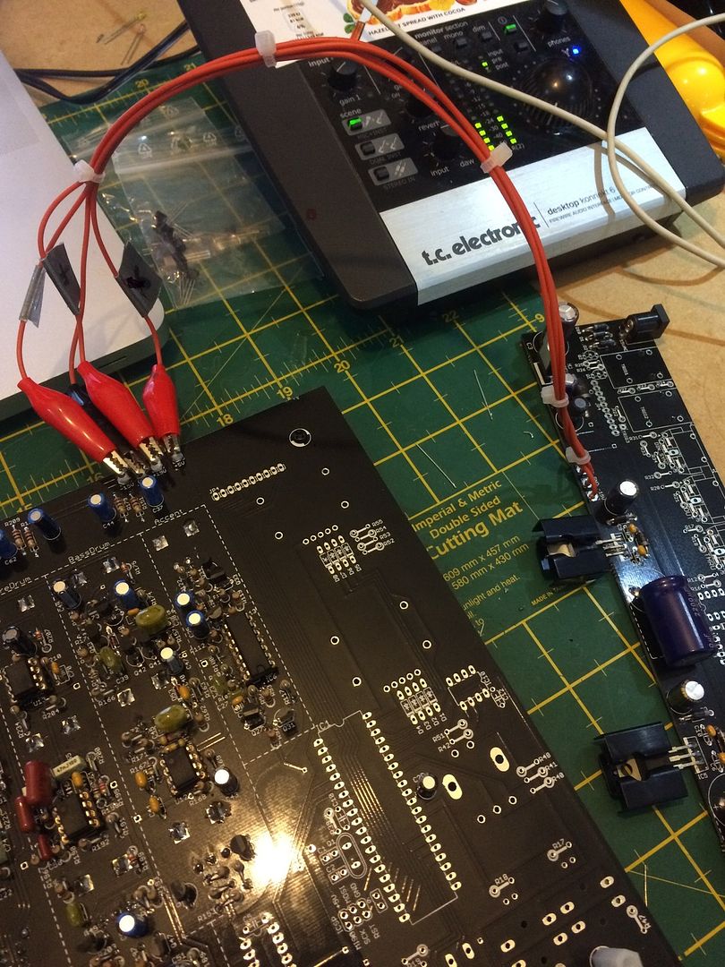
I've found it very useful to cut up a Molex header into four 'prongs' and solder them in place of the 15+, 15-, gnd and 5+ input on the main board. I then soldered some croc clips to the wires from the IO board, this way when soldering components the power cables can be easily removed making it much easier to flip the board over and removes the risk of constantly bending the wires to their breaking point.
Example:
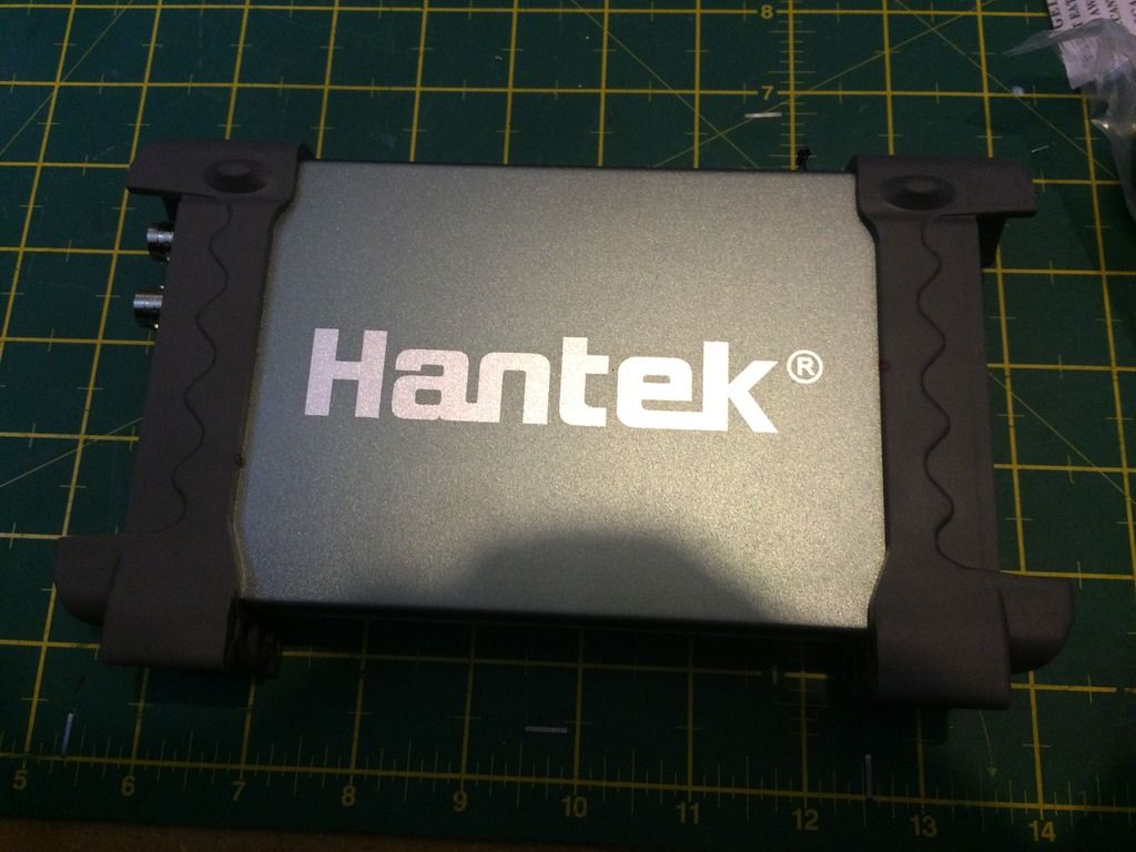
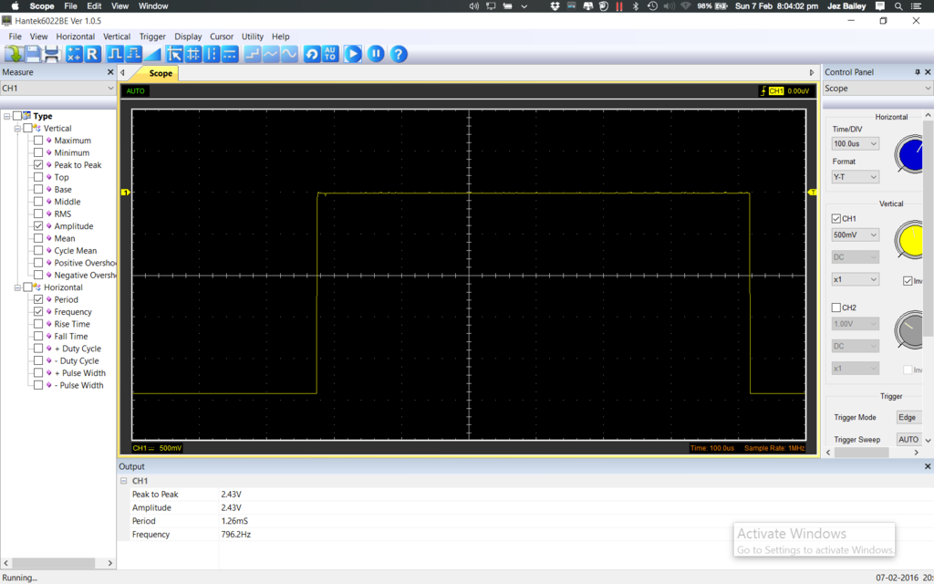
2. Hantek 6022BE oscilloscope works great for this application. This osc is a PC based osc however if you're a Mac user, like me, it runs fine in a virtual machine. I got this one on Amazon for about £47, but with Amazon they have a no questions return policy for 30 days after purchase and usually accept returns after this period anyway.
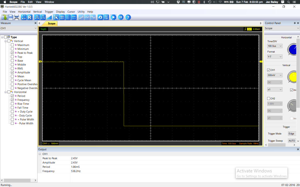
Here are some shots of the cymbal calibration measurements, notice at the bottom it gives you an exact period measurement which seems pretty accurate.
Peace.
Useful Building Tips
i socketed all ICs, used connectors for all cables, and didn't use the actual flatcables since they were uber short
for the power cables between the two boards, i used a 4-pin molex connector like the ones found in computer PSUs
here's a picture (click for uber-zoom):
i raised the sequencer switches with ~2.4mm by putting little chunks of plastic "plus-shaped" spacers (these are used for lining up ceramic tiles)
i used slices of thick paper (actually the carton-like paper from the capacitors) to put into the gaps around the switches, with the PCB mounted onto the front panel
(i actually placed the paper on the left/right sides instead, since they wiggled more sideways)
the BOM included 220ohm resistors for all LEDs
i tested them on 5V thru the 220ohm resistor - ..no way
i took a 10K pot and hooked it to a LED, starting from 10K down slowly..
above ~4K the LED was not very bright, and below 1K it was painful, especially when the LED blinks
so went for 3.3K resistors
i recommend trying your LEDs too before soldering the resistors.. don't just take my values for granted - different LEDs would need different resistance, so just try them out
Last edited by antto on Apr 23rd, '16, 07:04, edited 1 time in total.
Very usefull topic, nice work !
Yocto building tips by by Masuto is usefull too.
Best regards,
e-licktronic
Yocto building tips by by Masuto is usefull too.
Best regards,
e-licktronic
Best regards,
e-licktronic
e-licktronic
"Remove the encoders’ tabs before you solder them in!"
is stated in the link...
Why should I do that?
is stated in the link...
Why should I do that?
If you don't remove the little tab on the face of the encoder the tab will be in the way and won't let the encoder sit flush with the Yocto's faceplate. Being made out of aluminum, the tab comes off pretty easy. I used my Dremmel tool, or you could just file it off by hand.
So why has this important info not been mentioned anywhere else or in the tutorial? Sigh. I have allready soldered everything. :-/
don't worry... you can just knip it off with a sharp side cutter even it's already been soldered. (don't forget to protect your eyes!)drifter7508 wrote:So why has this important info not been mentioned anywhere else or in the tutorial? Sigh. I have allready soldered everything. :-/
I have a dremmel tool as well, just don't want to get debris over the board Have to shield it off with tape and paper.
flush side cutter's are amazing...
Cowbell Tip
Version 1.0 PCB, skip the listed values and stuff the following parts:
R44= 100K
R45= 68K
Skip trying to adjust via scope, use a DMM set to HZ and adjust the following to ground.
TM1= 526-540HZ
TM2= 800HZ
Clap should sound like it should...
Version 1.0 PCB, skip the listed values and stuff the following parts:
R44= 100K
R45= 68K
Skip trying to adjust via scope, use a DMM set to HZ and adjust the following to ground.
TM1= 526-540HZ
TM2= 800HZ
Clap should sound like it should...