
See "Slide Switch Grounding?" => viewtopic.php?f=16&t=720
This reduces (conga) noise a lot.
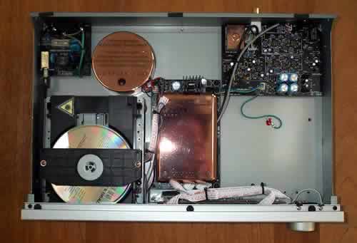
Internal power supply and PSU mod
-
Get the latest unofficial Yocto V1 firmware here.
Be sure to check the revised manual.
Leave your comments in this thread.

deejayraoul wrote:I kept my external power supply, didn;t do any scientific comparison, but it was obvious.EchoBoy wrote:@deejayraoul: Did you keep the external supply option to make a SNR comparison between external and internal supply?
I did not have time to investigate on my hum issue yet. Sorry Jeroenbvo for not having replied earlier.
In my case the hum is present on all outputs, whether instruments are played or not. This hum also exists with the external supply but >10dB quieter which makes it acceptable.
For now I suspect radiation from the toroidal transformer.
I gues i need to
find a shieldedtransformer (wich would be quie hard as the transformer hardly fits in the metal case at the moment)
ór
find a way to shield this transformer (does anyone know of a safe way/material to do this?)
ór
deal with the noise
ór
go back to the external power supply.
About the noise (the hum at 50/60 Hz) the true "Achilles heel" in my case were once again the flat cables that carry the audio signal to the two printed circuits. It can happen that some wires may become broken, while maintaining an unstable connection that causes a strong hum. After mounting the yocto in the container sold by Kacper, I had to replace it again these cables for the fourth time. About the transformer, i think that the resin toroidal are the best. You can be further shielded with a Faraday cage, stealing the idea for this CD players I have at home.
About the flat cables: I'm using PSK multi-pin connectors for the connection between the IO board and the main board. It's a bit more work (even more if you do not have the fitting crimping tool like me), but I think it pays off, because of the looks and being able to disconnect the two boards at any time. For the power cable I used a molex connector.bmaximus wrote: About the noise (the hum at 50/60 Hz) the true "Achilles heel" in my case were once again the flat cables that carry the audio signal to the two printed circuits. It can happen that some wires may become broken, while maintaining an unstable connection that causes a strong hum.

This picture is very reassuring. Well made!
Nice !
Something like this may also work: https://www.don-audio.com/trafo-shield or you can get MU Metal in sheets from http://www.lessemf.com/mag-shld.html.
The enclosure would work, but make sure any toroid mounting don't touch the box.
The enclosure would work, but make sure any toroid mounting don't touch the box.

jeroenbvo wrote:
I have also connected the chassis ground to the PSU using a loop breaker intended to prevent earth/ ground loops to prevent hum when systems are interconnected.
What 2 diodes did you use for the ground loop breaker jeroenbvo?
1N4004's or 1n5818 or other schottky diodes?
The reason I ask is because at the top you mention 1N4004's and on your blog you say the 1N5***'s http://imgur.com/a/IeBch#3
Will this mod work for the Nava?
Also what is the benefit of changing the PSU into a full wave bridge/Full wave Rectifier (removing D1&2)?
Does this turn the PSU into DC?
Does this turn the PSU into DC?

Both set ups take an low voltage AC and convert it to DC. The difference between half and full wave rectified supplies is that the full wave has better ripple characteristics but requires a transformer secondary with a center tap. Those are generally only seen in internal transformers, external AC-AC bricks dont have a center tap. In this case, I am not convinced that an internal transformer is somehow better. Sticking a big ass magnet inside a tight case which leaks magnetic flux everywhere is probably going to cause more noise problems than it solveshofmann25 wrote:Also what is the benefit of changing the PSU into a full wave bridge/Full wave Rectifier (removing D1&2)?
Does this turn the PSU into DC?
Thanks Altitude, always so eloquentAltitude wrote:Both set ups take an low voltage AC and convert it to DC. The difference between half and full wave rectified supplies is that the full wave has better ripple characteristics but requires a transformer secondary with a center tap. Those are generally only seen in internal transformers, external AC-AC bricks dont have a center tap.hofmann25 wrote:Also what is the benefit of changing the PSU into a full wave bridge/Full wave Rectifier (removing D1&2)?
Does this turn the PSU into DC?
Ok so knocked up 2 options (Using the NAVA PSU [if these posts need to be moved to the NAVA Hardware thread a moderator could do it. I don't know how, Either way it'll work on both right?]).
The probably have mistakes
And maybe there are two people who have tried one of each?
So the first option is better because it has 'better ripple characteristics'?
Full Wave Bridge & Loop Breaker?

Full Wave Rectifier & Loop Breaker ?

jeroenbvo wrote this but I'm still not 100%
-The rectification efficiency of full-wave rectifier is double of that of a half-wave rectifier.
-The ripple voltage is low and of higher frequency in case of full-wave rectifier so simple filtering circuit is required.
-Higher output voltage, higher output power and higher Transformer Utilization Factor (TUF) in case of a full-wave rectifier.
-In a full-wave rectifier, there is no problem due to dc saturation of the core because the dc current in the two halves of the two halves of the transformer secondary flow in opposite directions.
Thanks