
Many thanks for the advice Patrick.Patrick wrote: Your soundcard oscilloscope must have a calibration /specially voltage regulation.
Or you must feed a 1v signal to get a voltagebaseline on your pc.
A analog oscilloscope cost arround 50€ on ebay and its a must have for troubleshooting
Noise section trimmer voltage?
jmx303 wrote:Just another question for clarification, as I am also measuring approximately 260mV at least (and I am absolutely sure that I did not pick the wrong parts (R127 is 4.7k for now):
Is it really correct to change R127 already now to 47k, at this point, even if the Noise part is the only part finished so far (besides the Power Supply of course)? Wouldn't the value measured change under load (i.e. if the rest of circuits are finished)? In that case I would continue building the rest first and check again at the end. But if I am getting this wrong and the value does not change under load, it would make sense to change the value now.
When did you guys change your R127? Right at the point you measured for the first time or after everything was built?
How should I proceed?
Cheers,
jmx.
Sooo... After doing a quick count of components I found I had put a 47k in R127 instead of the 4.7k (Possibly because i was going off the image in the build guide)
So now, with the correct (according to the guide) value in, I'm getting the same 250mV as the others that have had difficulties... Hmm..

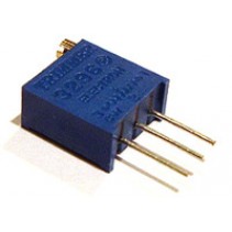
I have a 100k trimmer for r127.
And please dont use autorange on your DMM.
Doublecheck with a oscilloscope.
And please dont use autorange on your DMM.
Doublecheck with a oscilloscope.
Okay, I'll check mine with a scope. My DMM wasn't super expensive - about £35 which is I guess 45-50 Euro, no autorange.Patrick wrote:I have a 100k trimmer for r127.
And please dont use autorange on your DMM.
Doublecheck with a oscilloscope.
When you say you have a 100k trimmer for R127, do you mean you've put a trimmer instead of the resistor?
I'm not sure whether to carry on with the next section or not, or wait till I have the correct reading at the noise section..
Any official advice from the e-licktronic guys?
Hey 4teenth,
I removed R127 and replaced it with a 100k trimmer like this:
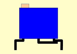
The middle leg is bent across and soldered to the leg below the trimmer screw, then both the outer legs are soldered in the PCB where R127 came out. Like the image below, although the middle leg on this example has been bent across the opposite way.
I laid the trimmer flat on the PCB with the legs bent at a right angle, this keeps the profile low. I will take a photo if this explanation is not clear enough.
I removed R127 and replaced it with a 100k trimmer like this:
The middle leg is bent across and soldered to the leg below the trimmer screw, then both the outer legs are soldered in the PCB where R127 came out. Like the image below, although the middle leg on this example has been bent across the opposite way.
I laid the trimmer flat on the PCB with the legs bent at a right angle, this keeps the profile low. I will take a photo if this explanation is not clear enough.
Hmm... Well, I may well end up doing something similar, although ideally I'd rather just have a value at R127 that gives me enough scope to adjust with the trimmer as in the instructions.lfo2vco wrote:Hey 4teenth,
I removed R127 and replaced it with a 100k trimmer like this:
The middle leg is bent across and soldered to the leg below the trimmer screw, then both the outer legs are soldered in the PCB where R127 came out. Like the image below, although the middle leg on this example has been bent across the opposite way.
I laid the trimmer flat on the PCB with the legs bent at a right angle, this keeps the profile low. I will take a photo if this explanation is not clear enough.
So, I guess I'm looking for reasons why some of us are not able to adjust to the value specified:
a) Innacuracies with DMM ?
b) tolerances/variance on the trimmer and/or other components?
c) Incorrect components somewhere?
d) Bad solder joints?
Well if you look at the Roland service notes for the 808 you will see that the noise circuit was revised on later versions. I guess that Roland encountered similiar problems during the early production phase. I stand to be corrected by the more knowledgable on this statement but... it is to do with component tolerences in this particular circuit design.4teenth wrote: Hmm... Well, I may well end up doing something similar, although ideally I'd rather just have a value at R127 that gives me enough scope to adjust with the trimmer as in the instructions.
So, I guess I'm looking for reasons why some of us are not able to adjust to the value specified:
a) Innacuracies with DMM ?
b) tolerances/variance on the trimmer and/or other components?
c) Incorrect components somewhere?
d) Bad solder joints?
I would suggest that you use a trimmer until you narrow down to the required resistance value for R127, then replace it with a resister of that value (if you would rather not just leave the trimmer).
I also changed R127 value 4.7K to 47K to get 130mV. Why is R127 value 4.7 K in the tutorial and why I had to change in order to get the correct value?
Count me in as having to change the R127 resistor as well...With the original 4K7 resistor in R127, the closest I could get to 130mv was about 200mv with the TM4 trimpot turned all the way..
Then I replaced R127 with a spare 47K resistor (multimeter-measured as about 48K)..And I could only get to about 138mv with the TM4 trimpot turned all the way..The 47K resistors in the kit mostly measure around 46K so using one of those probly would have done it..Instead I settled for a 1% 29K resistor, and I've got 130mv with TM4 turned allllmost all the way..
So this is because of variation/tolerance in the HFE value of the 2SC828 transistor?
If you have a multimeter that can measure HFE, maybe just measuring and finding the right transistor beforehand would be easiest? Any idea what the HFE range for the 2SC828 should be to get 130mv, so that there's no need to adjust resistors in R127?
If I understand it correctly, this is because of the added deviations of all the "5%" parts...So this is because of variation/tolerance in the HFE value of the 2SC828 transistor?