Call us:
+262693808816
Sign in
shopping_cart
(0)
Modules/Case
Parts
Assembly Guide
Forum
search
clear
Home
Popular Products
Quick view
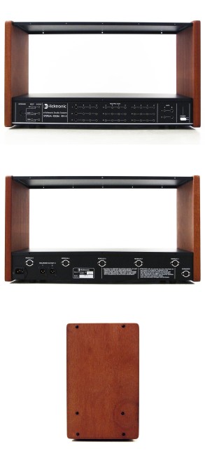
M-191-X Case
€489.00
Quick view
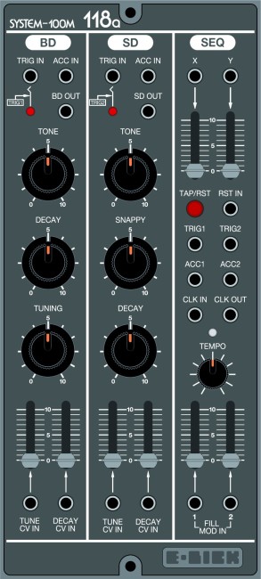
M-118a Drum Seq
€419.00
Quick view
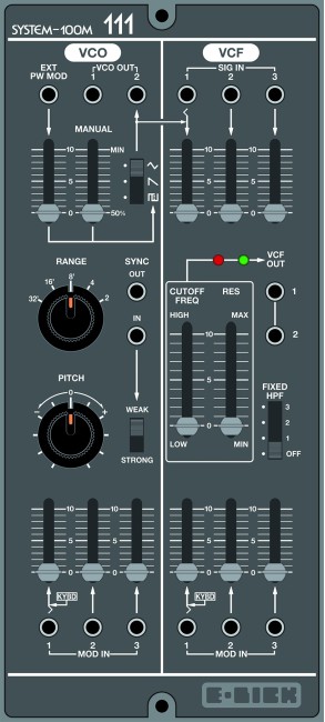
M-111 VCO VCF
€0.00
Available Soon
Quick view
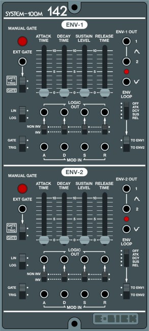
M-142 Dual ENV LFO
€0.00
Available Soon
Quick view
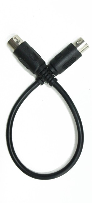
Roland system 100m Din8 cable
€9.90
Quick view
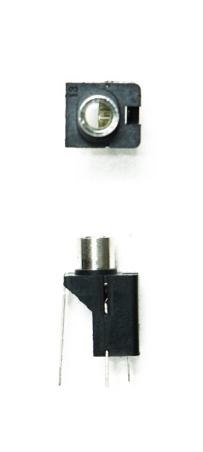
Roland system 100m Jack 3.5mm
€2.90
Quick view
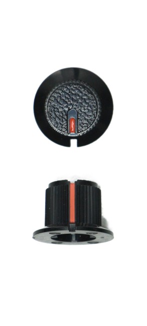
Roland system 100m knob big
€5.90
Quick view
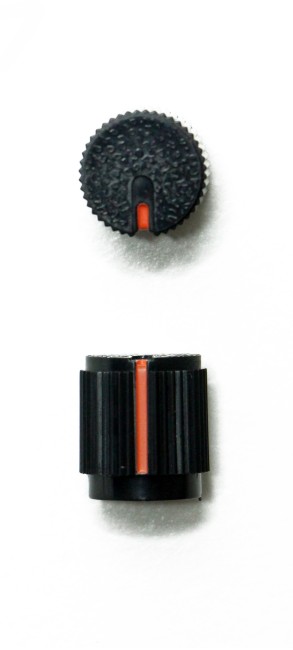
Roland system 100m knob small
€4.90
All products